The power supply in my media center PC bit the dust over winter break, so in the process of tearing everything apart to get the power supply out I had to remove an integrated audio amp supposedly rated at 50W per channel into 6 channels from what limited information I could find online. It was interesting to me for two reasons, its small size, and the fact that it is a digital (PWM) style of amp Fitting all this into something the size of my hand was impressive. So I took some pictures of it to see how it worked, and how they managed to fit the entire system into such a tiny space.
Right now the only documentation online is on their polish website http://pl.asus.com/Product.aspx?P_ID=sABpq9GJm3MbFOBA
Which doesnt mention anything about the power output of the amp. The first suspect item was the M-ATX power supply, which was rated for 300W and powered the amp through a standard 4pin connector. This would leave no power left for the rest of the computer, which at minimum is drawing 65W for the low power processor and motherboard. Regardless of ASUS’s rather overzealous marketing department the amp is still something interesting to look at. Also because it meets some decent specs:
Frequency response: 20Hz-20kHz, + / - 0.5dB (bandwidth)
SNR (signal to noise distance): 100 dB +
THD + N (total harmonic distortion factor of the noise): <0.2% (8?, 1W, 20Hz-20kHz)
While it is not terribly powerful, driving some efficient speakers with this makes me only want to turn up the volume a small ways before my room is uncomfortably loud.
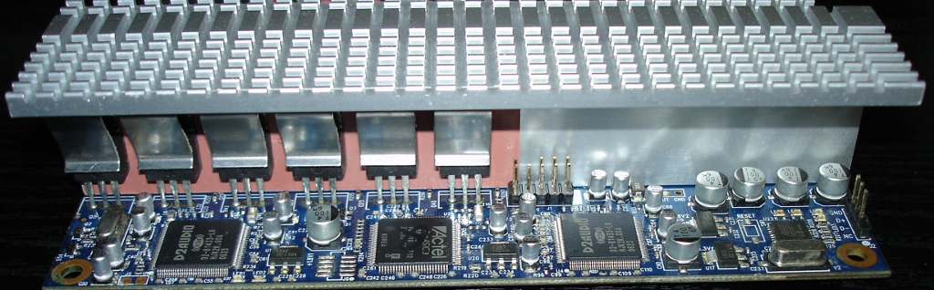
Onto the rest of the Amplifier, because it’s design is quite simple with very few parts, and I think the amplifier module might be capable of putting out 50W RMS into each channel. The hardware is nicely laid out, and all the power stages are very simple.
Power supply

This amp takes 12V in and runs it through a very simple forward converter, which steps the voltage up to +45 and -45V which then is sent to the positive and negative audio rails. This is a neat design for a computer power supply, especially if the PWM drivers are controlled using current mode control, as it can allow for some fluctuation of the audio power supply rails without messing too much with the standard 12V supply rail of the computer.
The Forward converter is a really simple textbook example, 2 fets switch separate coils in the transformer alternating, which allows power transfer at almost 100% of the cycle, requiring much smaller filter components.
PWM Stage.
The output stage is also very simple, each speaker is fed through a half bridge, consisting of two mosfets, which then goes through a very simple single stage LC filter consisting of a 200p cap and what is probably a 33.3uH inductor. There also is what looks like a very small shunt resistor, which might be measuring the output current and feeding this back into the proprietary driver ICs. The sub-woofer channel does away with the filter capacitor and doubles the inductor value Since the sub channel only needs to operate below ~100hz it does not need much filtering.
The really interesting stuff happens in the controller chips, which are made by D2 Audio, here they do some real time DSP, active noise shaping and speaker feedback to help equalize the output. Since there are not publicly available datasheets (sadly) we cant really see what goes on inside, but I am sure it is interesting.
On the other side of the heatsink you can see the other half of the mosfet drivers for each channel.