
And a quick libusb howto
I picked up a media center PC off ebay a year or two ago and used it every day, but I never bothered to get a Small USB status display to work on the front. I set out a few weeks ago to write a working driver and get the display operational. Using some libusb magic and a user space application to communicate with the display I designed a simple clock that had full color image backgrounds, freetype font rendering of the time, and many other possibilities.
For a link to the source code go to my google code project for this DAVA33Display
A little bit of background on the display
The display is a 320x240 24bit display built into an ASUS DAV A33 media center PC. It was never released officially in the USA however I picked it up on Ebay. The sticker on the bottom labeled it as a MOXI HOME CINEMA HD DMR model HDDMR9000. Basically it was a stripped down A33 media center, it is a pretty nice unit, and it's best feature is a built in 300W 5 channel digital audio amplifier. It also included a dvd drive, lots of AV inputs and outputs, a lirc compatible IR receiver and two HD tuners. Everything worked out of the box except for the small display on the front and thus my quest.
Reverse Engineering the display communications
The display communicated with the computer through a small user space application on windows, I resolved to sniff this communication. After a little bit of googling I found several USB protocol sniffers, I would have liked to use Snoopy pro as it was gpl'd however since I had vista installed I could not use it, but I found a trial of a neat application called USB Port Monitor
I set this up to start sniffing when I plugged in the display, and I was then able to sniff out all the usb packets going between the display and the computer. I plugged in the display, captured several seconds of logs and then stopped the capture and analyzed the data.
On the linux side I used wireshark to sniff the USB comms. Under ubuntu you can run wireshark as root and start sniffing on a USB controller to gather the data over the bus. However this did not work very well as wireshark only captures part of the data from each packet, thus limiting the debugging capabilities but it was still a useful tool. It is necessary sometimes to run the following command to enable USB debugging in the kernel so that libpcap can sniff the usb data for wireshark.
$sudo mount -t debugfs nonedebugs /sys/kernel/debug
First some Linux poking at the display. To discover the display I ran
$lsusb
which returned
ID 1043:82b2 iCreate Technologies Corp.
I then did some more poking around running lsusb with the -v option to show details about the device.
A little about USB protocols
Usb devices plug into one port, however they can have several different logical endpoints and configurations. So for example you can think of each endpoint as something like a port at a host that you can write or read from depending on it's configuration. There are different types as well including control ports or bulk endpoints. These are written to and can do different things on the device.
You can take a look at the different configurations and endpoints on the a device by running
$ sudo lsusb -v
This will return detailed information about each device on the usb bus.
Figuring out the device configuration
The output from lsusb -v on my display revealed the following information:
Bus 001 Device 005: ID 1043:82b2 iCreate Technologies Corp.
Device Descriptor:
bLength 18
bDescriptorType 1
bcdUSB 2.00
bDeviceClass 0 (Defined at Interface level)
bDeviceSubClass 0
bDeviceProtocol 0
bMaxPacketSize0 64
idVendor 0x1043 iCreate Technologies Corp.
idProduct 0x82b2
bcdDevice 0.01
iManufacturer 16 ASUSTek
iProduct 32 ASeries Device
bNumConfigurations 1
OTG Descriptor:
----------clipped------------
Interface Descriptor:
bLength 9
bDescriptorType 4
bInterfaceNumber 0
bAlternateSetting 0
bNumEndpoints 2
bInterfaceClass 8 Mass Storage
bInterfaceSubClass 255
bInterfaceProtocol 255
iInterface 0
Endpoint Descriptor:
bLength 7
bDescriptorType 5
bEndpointAddress 0x81 EP 1 IN
bmAttributes 2
Transfer Type Bulk
Synch Type None
Usage Type Data
wMaxPacketSize 0x0200 1x 512 bytes
bInterval 0
Endpoint Descriptor:
bLength 7
bDescriptorType 5
bEndpointAddress 0x02 EP 2 OUT
bmAttributes 2
Transfer Type Bulk
Synch Type None
Usage Type Data
wMaxPacketSize 0x0200 1x 512 bytes
bInterval 0
Interface Descriptor:
-----------clipped--------------
The Important things from the above are the device and manufacture ID's the configuration and the endpoint address descriptor. This defines how we communicate with the device. On this device there are also other endpoints however I will not concern myself with them as I do not need to communicate with the other interfaces.
Now I had captured as much data as I could about my device, including the actual data transfers using the USB sniffer software. Using this I started reading through the captured packet data.
I noticed a pattern, and a very important string in the communications.
Basically the computer (host) would send a short packet to the device, this would always begin with the byte code USBC and then some changing data
USBC (some data follows) B7 0C 00 00 00 00 01 00 00 00 0C E6
02 00 01 00 00 00 03 84 20 00 00 00 00 00 00
Which the device would respond with a similarly formatted response that always started with
USBS (some data follows)
After some more googling I found that this corresponded to the Bulk Only Transport (BOT) specification as defined in the USB standard. It is defined here:<a href="http://www.usb.org/developers/devclassdocs/usbmassbulk10.pdf" target="blank" title="http://www.usb.org/developers/devclassdocs/usbmassbulk10.pdf"> http://www.usb.org/developers/devclassdocs/usbmassbulk10.pdf
Basically the host sends some command packet (Command block wrapper) defining a transaction ID some data length, an address and a string at the end (which I guessed might be some additional level of addressing) The host then either sends a send request with the data or reads from the endpoint for the requested length of data.
Taken from the usbmassbulkto.pdf spec:
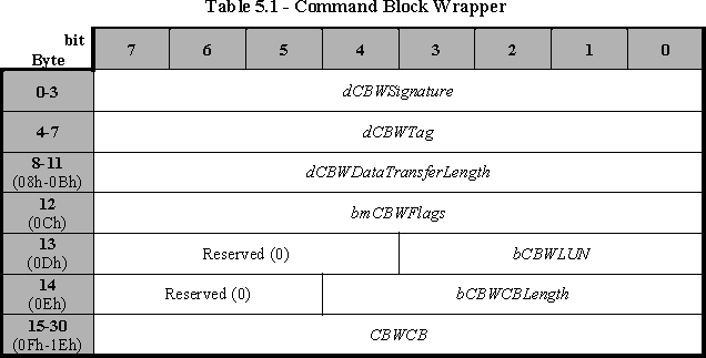
At the end of the read or write the host then sends or reads a response packet where a communication finished packet is communicated. All data is sent to endpoint 0x02 and all reads are from the read endpoint 0x82 as defined in the USB endpoint configuration for the device.
After understanding how the BOT specification worked I surmised that the display was written to using several usb data transactions:
To update the display requires 3202403 bytes of data.
The display BOT transport sends the following Command block wrappers:
55 53 42 43 B7 0C 00 00 00 00 01 00 00 00 0C E6 02 00 01 00 00 00 03 84 20 00 00 00 00 00 00 CBW sent
 0x10000 send bytes of image data
55 53 42 53 B7 0C 00 00 00 00 00 00 00 receives command block response

55 53 42 43 B8 0C 00 00 00 00 01 00 00 00 0C E6 02 00 01 00 00 00 03 84 20 01 00 00 00 00 00
 0x10000 send bytes of image data
55 53 42 53 B8 0C 00 00 00 00 00 00 00 read command block response

55 53 42 43 B9 0C 00 00 00 00 01 00 00 00 0C E6 02 00 01 00 00 00 03 84 20 02 00 00 00 00 00
 0x10000 send bytes of image data
55 53 42 53 B9 0C 00 00 00 00 00 00 00 read command block response

55 53 42 43 BA 0C 00 00 20 84 00 00 00 00 0C E6 02 00 00 84 20 00 03 84 20 03 00 00 00 00 00
 0x8420 bytes of image data
55 53 42 53 BA 0C 00 00 00 00 00 00 00 read command block response
This Was all the data to send an image update. If you notice WBWCB fields at the end change for each field indicating a new location to write the data to.
Also the total amount of data sent adds up to 3202403 + 32 bytes of data, some further exploring near the beginning of the first packet of data showed some non image data that was sent, I copied this over to ensure that what I sent was exactly what the original driver sent.
Here is a snip of the beginning of the first packet. You can see a little ways down there starts to be a 3 byte pattern that repeats, this is the raw RGB image data. I found out later after some experimenting that this header was required for the display to work properly. The rest of the data transferred was raw image data, I verified this by saving the raw data and importing it into GIMP as a raw image data file and saw what was on the display in gimp.
 02 00 20 00 20 84 03 00 00 00 00 00 40 01 F0 00
 00 00 01 00 00 00 00 00 00 00 00 00 00 00 00 00
 08 42 8C 00 39 84 08 42 8C 00 39 84 08 42 8C 00
 42 84 08 42 8C 00 39 84 08 42 8C 00 42 84 08 42
 8C 00 42 84 08 42 8C 00 42 84 08 42 8C 00 42 84
 08 42 8C 00 42 8C 08 42 8C 00 42 84 08 4A 8C 00
Now we must try writing our own driver.
Writing a driver using LibUsb
For a link to the source code go to my google code project for this <a href="http://code.google.com/p/dava33display/" target="blank">DAVA33Display
First a word of caution, libusb does not have the worlds most stellar documentation. However after lots of extensive googling and reading the limited libusb docs I had the following overview of libusb. (their official docs are here: http://libusb.sourceforge.net/doc/ )
- Find the display I want to communicate with using its VID and PID
- Iterate over the USBFS to find the device descriptor
- Open the device
- Set the device configuration
- Perform some endpoint reset messages just in case (might not actually be necessary)
- Send and receive messages using the libusb Api to the different bulk endpoints. to send updated screens to the display.
- close up the device and exit cleanly when done.
For all the details I recommend reading over the code.
Once the device is all setup I could easily create a buffer in memory, load in image data and then output it to the display using a simple sequence of
writedata(0x02, &command, sizeof(command));
writedata(0x02, imgdata, 0x10000);
readdata(0x81, &resp, 0x0d);
To write the command, then the image data, and the finally read the display's status response.
Finally to make a clock I used several different system api's, the gd library which has excellent documentation and can be found at
http://www.libgd.org
This basically was used to create picture in memory, rendered on some text using ttf fonts, and then I made a small wrapper function to convert this picture to a format which was written directly to the display.
The final result was this clock: