
Well again, our church needed something that is not available. With all the tours and moving around that they do, they use a lot of remote control cameras to film the audience. Their budget is not large, however they do have nice cameras, and a need to control them.The solution is a wireless based control system which can be easily transported, durable, and reliable. It also needed to offer a fine level of control, IE proportional control on all axis.
To further develop this system, since only a few units were scheduled was to use cheap prototyping and off the shelf hardware with a very small amount of custom hardware. Choosing an Arduino for the controller to camera interface, and a wireless playstation controller I started developing a high quality wireless camera controller.
I chose the play station controller due to its durability and inexpensive cost. Stopping at frys electronics I found a wireless playstation controller for $24, after testing it I found it worked well even at 200 feet away, plenty more distance than my application needed.
After doing some research on interfacing play station controllers to microcontrollers, I found the best source to be over at curious inventor's guide to interfacing PS2 controllers. Also I found some code over at the Arduino wiki however it did not include analog support. Rewriting the PSX library I developed the PSX analog library which has a much greater functionality including force feedback, and analog control. It is somewhat bigger, however in my opinion worth it. Finally I had to reverse engineer the pan tilt head and the Sony EX-1 connector and pinout.
If there is a demand for these I could start making them, Total cost would be around $150 each without the pantilt head. Thats a lot cheaper than competing solutions. Take a look at http://www.varizoom.com/products/controls/vzrockex.html it costs over $300 just to control the lense and it has no where near the range of this system!!!!! If you are interested shoot me an email at  and we can see what can be arranged.
Pan Tilt Head
The Pan tilt heads we used are a generic low voltage pan tilt head that runs off 6V. They seemed easy to interface at first, however there was a trick as they had built in electronic limit stops. It is controlled by 4 wires, 2 for pan, 2 for tilt. However whoever designed this was kind of crazy as whenever a limit was reached which ever wire was for that direction would get shorted to ground. Not the smartest, and the original remote had a problem because if either axis was at the limit, the remote could only go away from that direction and if the user tried to go in two directions which included the limit direction, the head would not work.
I knew this was a simple dual H bridge controller, and built 2 PWM channels to control the pan tilt head. This enabled the pan tilt head to have fully proportional control on both axis even if one was in limit.
To get around the shorting to ground at limit, I simply put a 1K resistor between the output of my micro controller and the input to the pan tilt head.
Sony XDCAM EX-1 remote zoom control pinout
This part was tricky as it required reverse engineering the connector, not too hard, until you start thinking that if you break something you just ruined a 7000 dollar camera. Well after scoping and doing some testing I found the connector had one analog input for the zoom, and 2 digital inputs for the record and A switches on a remote which were just pulled low to activate. A summary of my research is below:
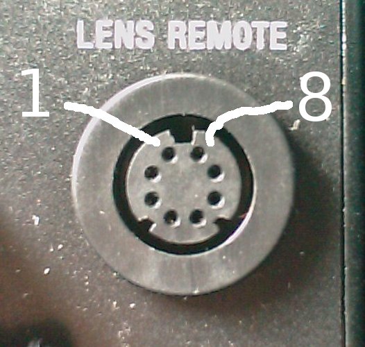
| Pin Number | Pin Function |
| 1 | na |
| 2 | button common gnd |
| 3 | aux button signal +3.3v pull low to activate |
| 4 | rec button signal +3.3v pull low to activate |
| 5 | unknown |
| 6 | zoom +3.3v |
| 7 | zoom ctrl |
| 8 | zoom - (gnd) |
Note all signals are 3.3V signals, and all button signals are pulled to ground to activate. Quite easy to implement.
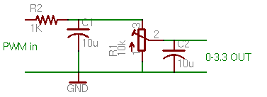
Finally the zoom signal is an analog voltage. This is implemented by using a pwm signal of the micro and filtering it. Initially I used a simple 1 stage RC filter, however there was too much ripple in the output causing the lense to have a shuddering effect when zooming in and out This was fixed by adding an additional filter capacitor on the last output stage which made everything very smooth. The circuit is as follows:
Finally the code. For this to run you also need the PSXanalog library which I also designed.
From the code it is pretty easy to see what pins get hooked to what devices.
The Finished Product:
<img src="/img/projects/ex1wireless/ex1pantilt1.JPG" border="0" />
A video showing the operation:
The Arduino code is as follows:
/* Pan tilt controller library (EX1Pantilt.pde)
Written by: Kieran Levin Mar 8th, 2009
This program is free software: you can redistribute it and/or modify
it under the terms of the GNU General Public License as published by
the Free Software Foundation, either version 3 of the License, or
(at your option) any later version.
This program is distributed in the hope that it will be useful,
but WITHOUT ANY WARRANTY; without even the implied warranty of
MERCHANTABILITY or FITNESS FOR A PARTICULAR PURPOSE. See the
GNU General Public License for more details.
You should have received a copy of the GNU General Public License
along with this program. If not, see <http://www.gnu.org/licenses/>.
/
#include "Psx_analog.h" // Includes the Psx Library
#define dataPin 14
#define cmndPin 15
#define attPin 16
#define clockPin 17
#define motorup 9
#define motordown 10
#define motorleft 5
#define motorright 6
#define zoom 11
#define rec 12
#define mode 13
#define center 0x7F
Psx Psx; // Initializes the library
void setup()
{
Psx.setupPins(dataPin, cmndPin, attPin, clockPin); // Defines what each pin is used
// (Data Pin #, Cmnd Pin #, Att Pin #, Clk Pin #)
Psx.initcontroller(psxAnalog);
//setup motoroutputs
pinMode(motorup, OUTPUT); // Establishes LEDPin as an output so the LED can be seen
pinMode(motordown, OUTPUT); // Establishes LEDPin as an output so the LED can be seen
pinMode(motorleft, OUTPUT); // Establishes LEDPin as an output so the LED can be seen
pinMode(motorright, OUTPUT); // Establishes LEDPin as an output so the LED can be seen
pinMode(rec,INPUT);
pinMode(mode,INPUT);
digitalWrite(rec, LOW);
digitalWrite(mode, LOW);
Serial.begin(9600);
Serial.println("Raw controller values");
// wait for the long string to be sent
delay(100);
}
void loop()
{
Psx.poll(); // Psx.read() initiates the PSX controller and returns
/ Serial.print("\n"); // the button data
Serial.print(Psx.Controllermode, HEX); // prints value as string in hexadecimal (base 16)
Serial.print(',');
Serial.print(Psx.digitalbuttons, HEX); // prints value as string in hexadecimal (base 16)
Serial.print(',');
Serial.print(Psx.Rightx, HEX); // prints value as string in hexadecimal (base 16)
Serial.print(Psx.Righty, HEX); // prints value as string in hexadecimal (base 16)
Serial.print(Psx.Leftx, HEX); // prints value as string in hexadecimal (base 16)
Serial.print(Psx.Lefty, HEX); // prints value as string in hexadecimal (base 16)
*/
delay(25);
////// output analog values to correct pins
if (Psx.Lefty > center+2)
{
analogWrite(motorup,(Psx.Lefty - 0x80) * 2);
digitalWrite(motordown, LOW);
}
else if (Psx.Lefty < center-2)
{
analogWrite(motordown,(0x7F - Psx.Lefty) * 2);
digitalWrite(motorup, LOW);
}
else
{
digitalWrite(motorup, LOW);
digitalWrite(motordown, LOW);
}
if (Psx.Leftx > center+2)
{
analogWrite(motorleft,(Psx.Leftx - 0x80) * 2);
digitalWrite(motorright, LOW);
}
else if (Psx.Leftx < center-2)
{
analogWrite(motorright,(0x7F - Psx.Leftx) * 2);
digitalWrite(motorleft, LOW);
}
else
{
digitalWrite(motorleft, LOW);
digitalWrite(motorright, LOW);
}
analogWrite(zoom,0xFF - Psx.Righty);
if (Psx.digitalbuttons & psxRight)
pinMode(rec,OUTPUT);
else
pinMode(rec,INPUT);
digitalWrite(rec, LOW);
if (Psx.digital_buttons & psxDown)
pinMode(mode,OUTPUT);
else
pinMode(mode,INPUT);
digitalWrite(mode, LOW);
}